ITER
The Device
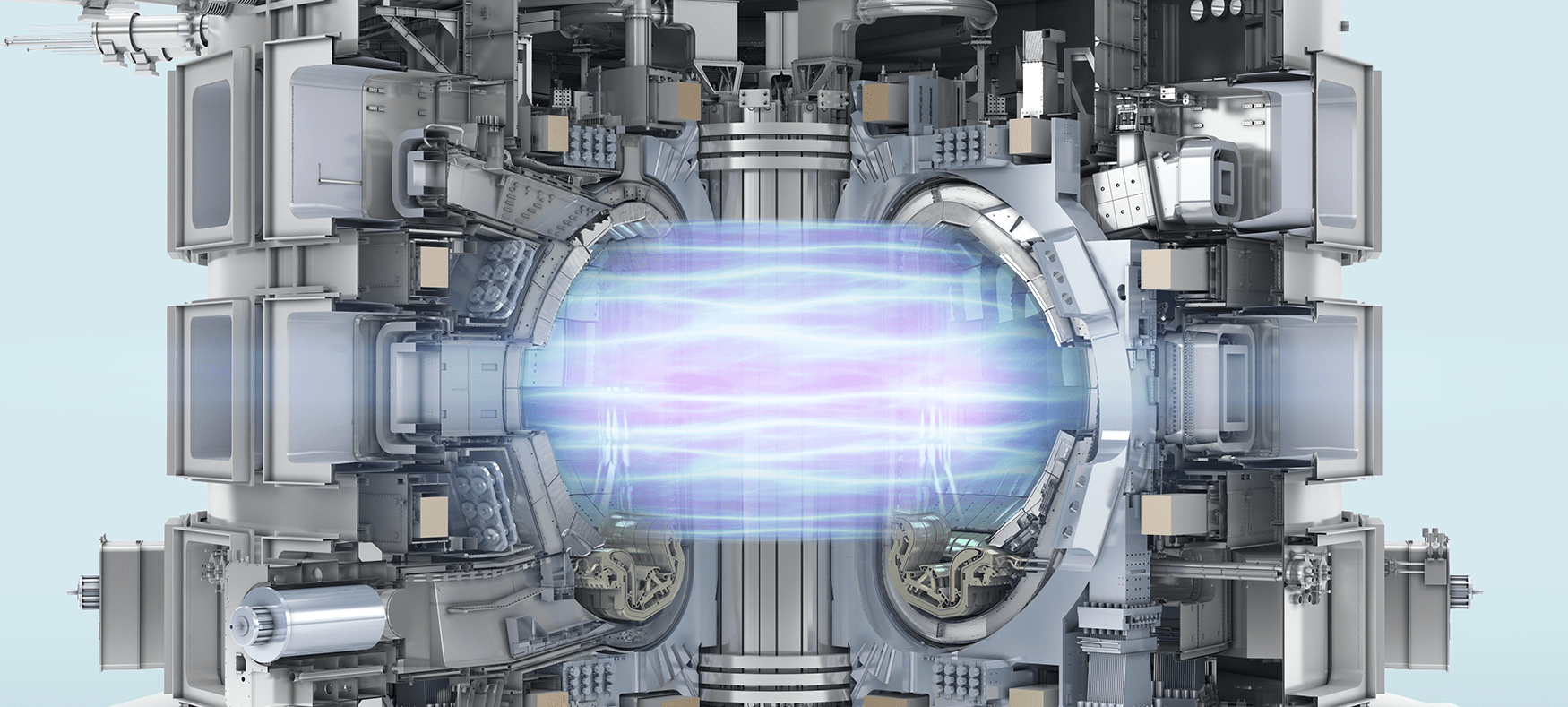
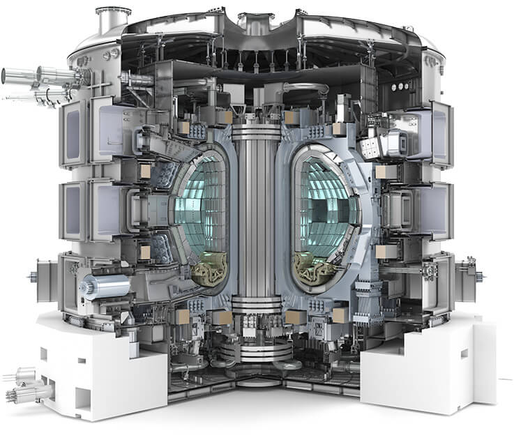
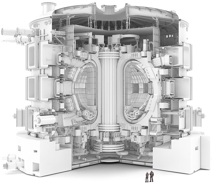
The ITER Device
Millions of components will be integrated in the biggest fusion device. The assembly of the device will be one of the most complex engineering operations. Each ITER Party is responsible for the manufacturing of distinct pieces of equipment. Europe is responsible for almost half of the components of the machine, while the remaining six Parties will have to deliver equally the rest. In Europe, their fabrication is the result of the collaboration between F4E, industry and research laboratories
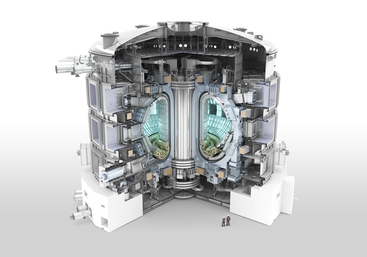
Some key figures about ITER
24 m high
30 m wide
23 000 tonnes
1 000 000 Number of components
830 m³ plasma volume
Discover some of the main ITER components and key technologies


Main ITER components and key technologies
- Magnets
- Toroidal Fields Coils
- Poloidal Fields Coils
- Pre-Compression Rings
- Vacuum Vessel
- Diagnostics
- In-Vessel
- Cryogenics
- Fuel Cycle
- Test Blanket Modules
- Remote Handling
- Antennas and Plasma
Engineering - Neutral Beam and
Electron Cyclotron

Magnets
ITER will rely on a sophisticated system of superconducting magnets consisting of the central solenoid, which can be described as its backbone; the correction coils, which will reduce magnetic errors created due to the location and geometry of other coils; 6 Poloidal Field coils responsible for the shape and stability of the plasma, and 18 Toroidal Field (TF) coils which will create a magnetic cage to entrap the hot gas. To cope with the fatigue of the TFs and the deformation resulting from the powerful magnetic fields, 9 pre-compression rings will be supplied. Three of them will be placed on top of the TFs and three below them. An extra set of will be manufactured as spare in case there is a need in future to replace the lower set. Europe is involved in the manufacturing of the TF and PF coils, plus the Pre-Compression Rings.
Toroidal Fields Coils
In total 18 TF coils will operate in the ITER device to create a powerful magnetic cage so as to confine the super-hot plasma. When powered with current (68 000 A) the magnetic field will reach up to 11.8 Tesla—about 250 000 times the magnetic field of the Earth! Each magnet measures 17 x 9 m and weighs 320 tonnes— as much as an Airbus A350. Europe will manufacture 10 of the TF coils. At least 40 companies and more than 700 people are involved in their production. Japan will provide 8 plus one spare. They will be the biggest Niobium-tin (Nb3Sn) magnets ever produced.
See the different layers of a TF coil by clicking on the poster.
Find out how Europe is manufacturing its TF coils by clicking here.
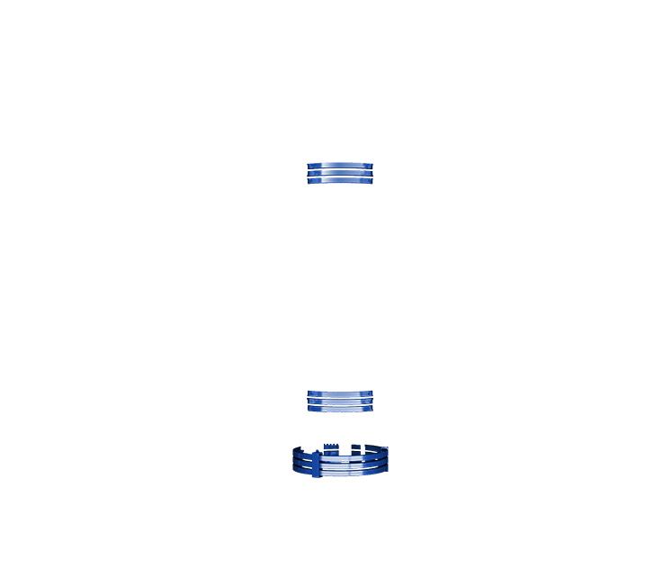
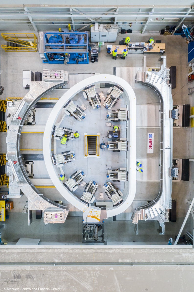
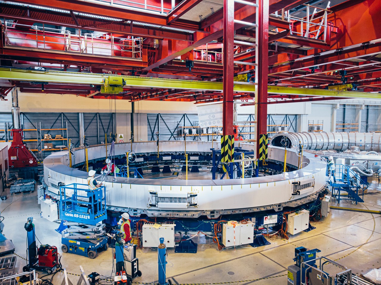
Poloidal Fields Coils
The ITER machine will operate with six PF coils, which will ensure the shape and stability of the super-hot plasma. Europe is responsible for five of them and Russia for one. Due to their impressive diameter and weight, four of the European PF coils, ranging between 17- 25 m in diameter and weighing between 200 – 400 t, will be manufactured in a factory located on the ITER site. The sixth coil is manufactured through a collaboration agreement signed in 2013 between Europe’s F4E and the Institute of Plasma Physics of the Chinese Academy of Sciences (ASIPP).
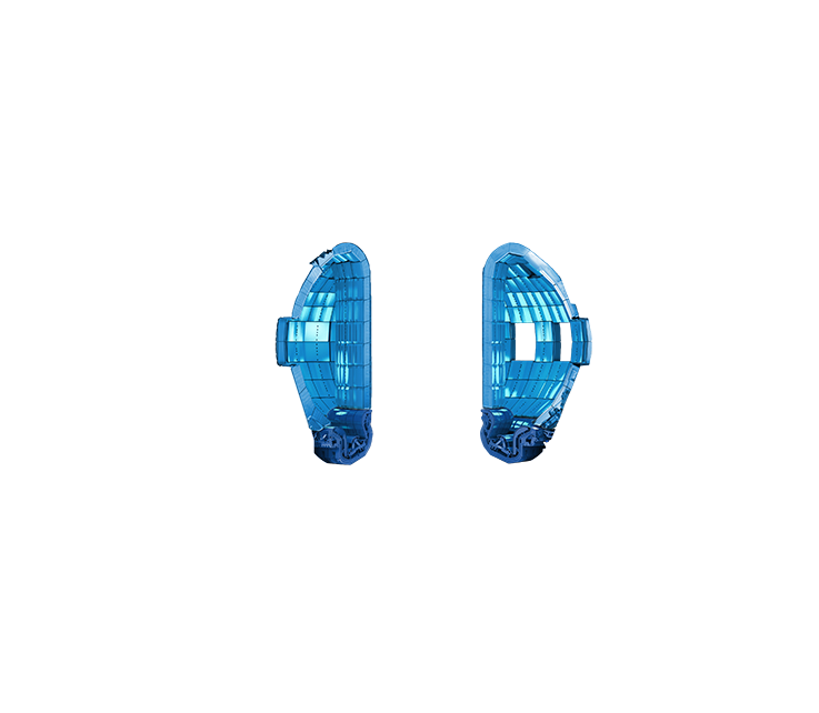
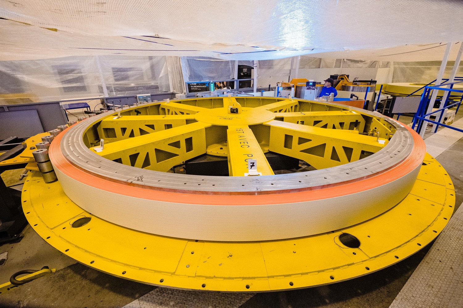
Pre-Compression Rings
To cope with the fatigue exercised on the Toroidal Field coils, and with the deformation resulting from the powerful magnetic fields, sets of Pre-Compression Rings will be installed. Three will be placed on top of the TF coils and three below them. An extra set of three will be manufactured as spare in case there is a need in future to replace the lower set. The fiberglass composite rings, consisting of more than a billion miniscule glass fibers, will be glued together by a high performances epoxy resin. They will have a diameter of approximately 5 m, a cross-section of nearly 300 mm x 300 mm and will weigh slightly more than 3 t.
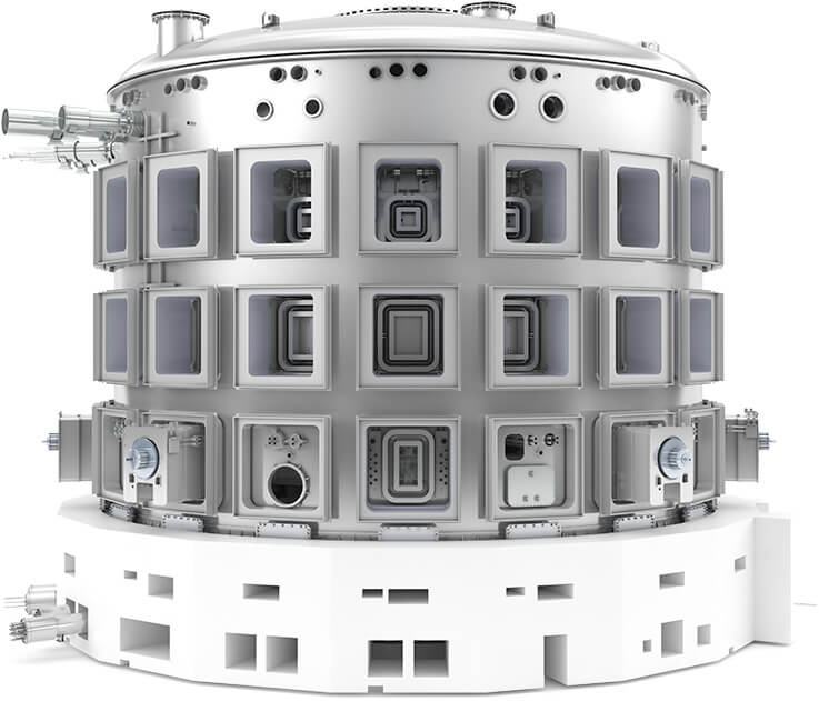
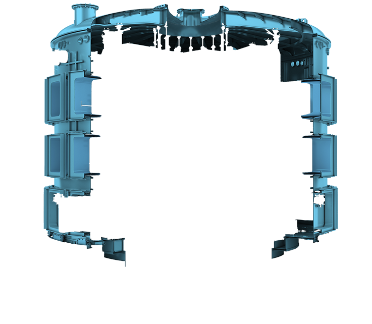
Vacuum Vessel
The ITER Vacuum Vessel is located inside the cryostat of the ITER machine. Its basic function is to operate as the chamber that will host the fusion reaction. Within this torus-shaped vessel, plasma particles collide and release energy without touching any of its walls due to the process of magnetic confinement. The vessel is made of nine sectors. Europe is responsible for five of them and Korea for the remaining four.
Watch the clip.
Each sector is 12 m high, 6.5 m wide and 6.3 m deep and weighs approximately 500 t. The weight of the entire component, when welded together, will reach a total of 5 000 t.
Diagnostics
The Diagnostics system will help scientists to study and control the behavior of the plasma, measure its properties and extend our understanding of plasma physics. This system will act as “the eyes and ears” of experts offering them insight thanks to a vast range of cutting-edge technologies.
ITER will rely on approximately 50 diagnostic instruments that will offer an unparalleled view of the entire plasma and ensure the smooth operation of the machine. Given the duration of the plasma pulse, which will be 100 times longer than any fusion device currently in operation, the diagnostic system will act as the guardian of the machine. Europe is responsible for roughly 25% of all Diagnostics in ITER.
In-Vessel
The extremely hot temperature of the fusion reaction will be mostly felt by the in-vessel components, otherwise known as plasma facing components, due to their direct exposure to high heat and neutron fluxes. The divertor consisting of 54 cassettes, located at the lower part of the machine, and the blanket consisting of the 440 modules, resembling to blocs covering the walls of the vacuum vessel, are the key components to be tested and manufactured in this area. Europe is responsible for the production of 54 divertor cassettes and 215 blanket modules.
Cryogenics
The ITER machine will have to cope with extreme temperature fluctuations. Cold helium will circulate inside the magnets to bring their temperature down to -269 ˚C in order to confine the super-hot plasma. The magnets, thermal shields and cryopumps will have to be cooled down and maintained with the help of one of the most advanced cryogenic systems to date. The cryoplant can be described as a massive refrigerator that will generate the freezing cold temperatures required for the fusion machine. Europe is responsible for the Liquid Nitrogen (LN2) Plant and its auxiliary systems.
Fuel Cycle
When ITER is operational the gases resulting from the fusion reaction will be pumped with the help of the six cryopumps from the lower part of the torus to the roughing system, where they will be processed and treated in a closed loop as part of the fuel cycle. Europe is responsible for the production of the cryopumps, valves and of the water detritiation tanks needed to recover the fuel so as to re-use it for another fusion reaction.
Watch the clip.
Test Blanket Modules
Experts working in the area of Test Blanket Modules Systems (TBMS) are among those who will use ITER to understand how tritium can be continuously bred in order to keep the fusion reaction going. Without a doubt, the lessons drawn will have significant implications towards the design of future fusion reactors like DEMO. In essence, they will be generating a new nuclear system and licensing using advanced materials and top fabrication techniques.
Europe is standing at the crossroads of two blanket concepts: the Helium-Cooled Pebble-Bed (HCPB) and the Helium-Cooled Lead Lithium (HCLL). The key difference lies in the type of material used for the tritium breeder. In order to choose which way to go for DEMO, the fusion machine that will follow ITER, it has been decided to test both concepts simultaneously in ITER.
In terms of the TBMs structural materials, Europe has set its hopes on EUROFER97, a newly developed reduced activation ferritic/martensitic (RAFM) steel developed in Europe, which provides adequate resistance to neutron irradiation, corrosion and with acceptable resistance at high temperatures.
Remote Handling
Remote handling helps us to perform a task without being physically present. For example, it is widely used in space exploration missions, underwater repairs or challenging maintenance works. The limited space inside the ITER machine together with the weight of the tooling and the exposure of some components to radioactivity will require the use of remote handling systems during maintenance. This area combines manufacturing and R&D in order to develop the appropriate tooling to operate with extreme dexterity and millimetric precision. Europe is responsible for the remote handling system of the ITER Divertor; Cask and Plug; Neutral Beam; In-Vessel Viewing.
To learn more about the Divertor Cassette Remote Handling system view the clip.
Antennas and Plasma Engineering
Large antennas will channel the electromagnetic waves generated by two heating systems- the Electron Cyclotron and the Ion Cyclotron- to heat ITER’s plasma. Electron Cyclotron Launchers will help scientists to target specific parts of the plasma by guiding the waves with the help of mirrors. In parallel, in order to optimise the ITER design and to achieve high plasma performance, a great degree of engineering is carried out in collaboration with companies and European fusion laboratories.
Europe is responsible for the Electron Cyclotron launcher, the Ion Cyclotron Antenna and the Electron Cyclotron control system.
Neutral Beam and Electron Cyclotron,
Power Supplies and Sources
To heat up ITER’s plasma at 150 million ˚ C, roughly ten times the temperature at the core of the Sun, we will need powerful heating systems using high-energy beams.
Neutral Beam Injectors
Two neutral beam injectors, with a third one as an optional upgrade during operation will be the power-horses of this system. Although this technology is routinely used for heating the gas in fusion devices, the size of ITER poses a set of challenges: particle beams have to be more powerful and individual particles have to travel faster to penetrate far into the core of the plasma. For this reason, negative ion based injectors are developed. The negative ions will be accelerated at 1 MV, a speed that no other neutral beam system has achieved. Once accelerated, they will be neutralised before they are injected into the ITER machine to heat the plasma. To master the technology challenges posed by the Neutral Beam systems, two test facilities have been set up. To learn more about SPIDER and MITICA click here.
Electron Cyclotron
This component works in a similar way to a powerful microwave oven that will heat up the ITER plasma. It converts electricity from the grid and supplies it to the gyrotrons, which by receiving energy generate strong electromagnetic waves to heat the hot gas. But here is a challenge: gyrotrons need high and stable voltages. This means that EC power supplies need to guarantee precise power and be able to switch it off in less than 10 micro-seconds.
To learn more about SPIDER and MITICA click here.